What it is
The board I build with is the ESP32-C3 SuperMini — the ESP32-C3 chip (made by Espressif) on a board barely bigger than a coin, with USB-C and a row of pins down each edge. It's a microcontroller: a tiny computer that runs one program on a loop, forever, controlling things in the real world. Unlike a classic Arduino Uno, it has a single-core RISC-V CPU at ~160 MHz, plenty of memory, and built-in Wi-Fi and Bluetooth LE — so your robot can be driven from your phone with no extra parts. The same radio also speaks ESP-NOW, Espressif's board-to-board protocol: two ESP32s talking directly with no router and no pairing — which is how you'll build your own robot remote control later in the series.
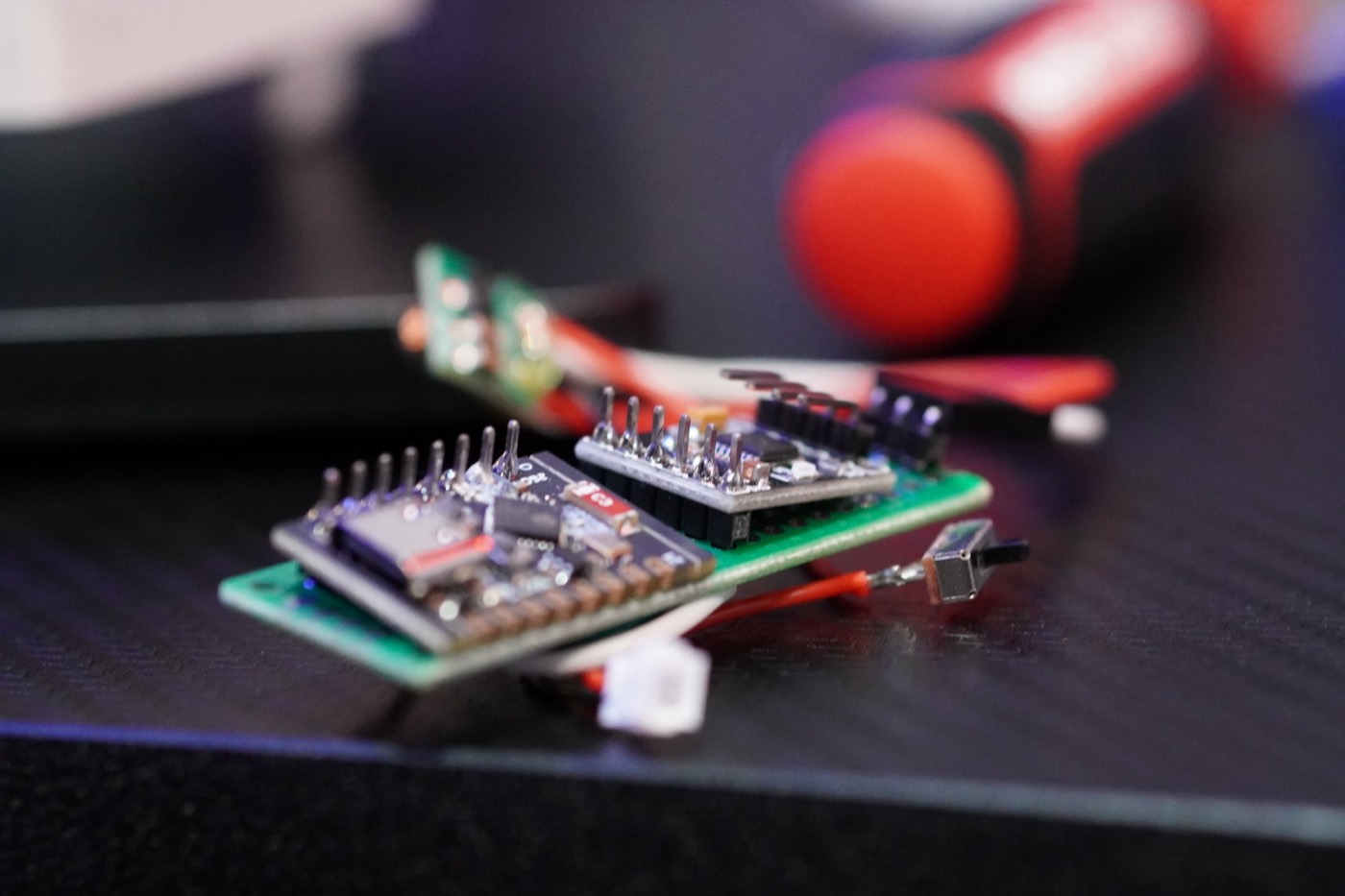
A few dollars of robot brain, in the flesh.
The bare minimum to use it
- It runs on 3.3 V logic — not 5 V. Power it over USB; never wire 5 V sensor signals straight into a pin.
- The numbered pins are GPIO — read buttons/sensors, switch things on and off, and output PWM to drive servos and motors.
- Program it with PlatformIO — describe the board once in
platformio.ini, plug in over USB, runpio run -t upload. - Start with Blink — get the onboard LED flashing and you've used everything you need to begin building.
Wiring (Blink)
Nothing to wire — just power the board over USB-C. The onboard LED is on GPIO 8 on the C3 SuperMini, and it's active-low (lit when the pin is LOW). Upload the sketch below and it blinks.
USB-C ──▶ ESP32-C3 SuperMini
                  └─ onboard LED ── GPIO 8 (built-in, active-low)
The C3 SuperMini pin map used across the minirobo builds — keep it handy as you wire up later episodes.
The code
Classic Blink for the ESP32. Copy it in, or download the sketch from the sidebar.
// minirobo EP1 — ESP32-C3 SuperMini Blink
#define LED 8            // onboard LED on the C3 SuperMini (active-low)

void setup() {
  pinMode(LED, OUTPUT);
  Serial.begin(115200);
  Serial.println("minirobo: hello from the ESP32!");
}

void loop() {
  digitalWrite(LED, HIGH);
  delay(400);
  digitalWrite(LED, LOW);
  delay(400);
}
What I wish I knew
- 3.3 V, always. Most of the cheap fried boards die here.
- "Charge-only" USB cables will betray you. If your PC can't see the board, swap the cable before you panic.
- You only get ~11 pins. A few are strapping pins (GPIO 2, 8, 9) the board needs at boot — save those for last.
- Don't power motors from the board — use a motor driver like the DRV8833 with its own battery.
- Upload stuck at "connecting"? Hold the
BOOTbutton while it starts, then release.